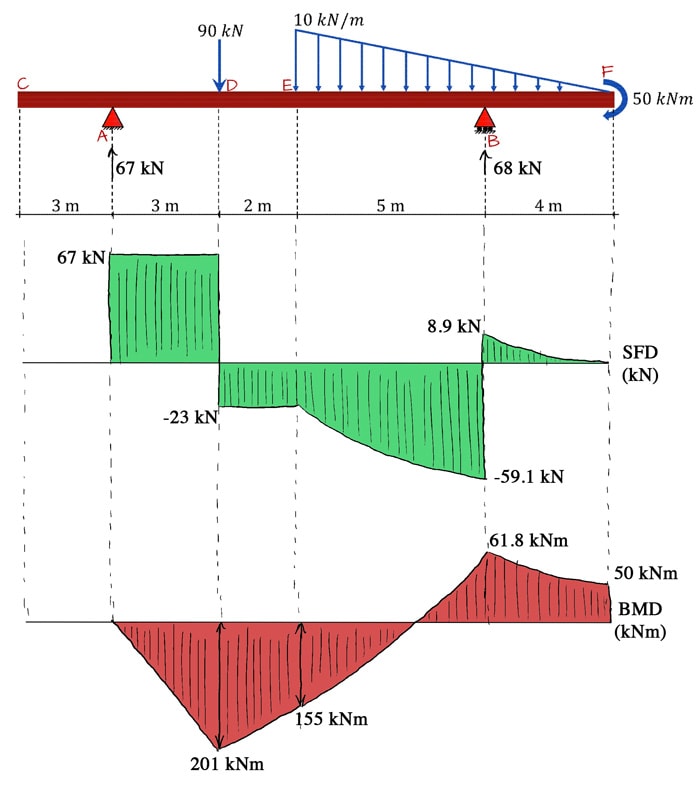
Shear bending degreetutors cantilever beams deflection
Table of Contents
Table of Contents
Are you struggling with how to draw shear and moment diagrams for your engineering projects? Do you find it difficult to understand the concept of shear force and bending moment? Look no further! This post will guide you through the process of drawing shear and moment diagrams, step by step.
When it comes to engineering projects, understanding how to draw shear and moment diagrams is crucial. However, many engineers struggle with this concept, leading to errors and incorrect calculations. Even the slightest miscalculations can lead to disastrous consequences. It’s important to have a solid understanding of the topic so you can avoid common mistakes.
The first step in drawing shear and moment diagrams is to understand the basic concept of shear force and bending moment. Shear force is the force perpendicular to an imaginary section of a beam, while bending moment is the internal moment that causes the beam to bend. Understanding this concept is crucial to successfully drawing shear and moment diagrams.
To begin drawing shear and moment diagrams, first, calculate the reaction forces at the supports of the beam. From there, calculate the shear force and bending moment at each point along the beam by analyzing the forces acting upon it. This information can then be used to plot the shear force and bending moment diagrams.
In summary, to draw shear and moment diagrams, you need to understand the concept of shear force and bending moment, calculate the reaction forces and analyze the forces acting upon the beam, and plot the diagrams accordingly.
How to Draw Shear and Moment Diagrams: Step by Step
As an engineering student, I found drawing shear and moment diagrams to be one of the more challenging topics in mechanics of materials. However, with practice and understanding, I was able to master the concept. Here are the steps I followed:
Step 1: Identify the reaction forces at the supports of the beam. This can be done by analyzing the external forces acting upon the beam.
 Step 2: Calculate the shear force and bending moment at each point along the beam. This can be done by analyzing the forces acting upon the beam to the left or right of the point in question.
Step 3: Plot the shear force and bending moment diagrams. The shear force diagram plots the shear force at each point along the beam, while the bending moment diagram plots the bending moment at each point along the beam.
Common Mistakes in Drawing Shear and Moment Diagrams
One common mistake in drawing shear and moment diagrams is failing to account for all forces acting upon the beam. It’s crucial to analyze all forces, including external forces and internal forces caused by shear force and bending moment.
Another mistake is failing to correctly calculate the reaction forces at the supports of the beam. This can lead to inaccurate shear and moment diagrams.
Shear Force and Bending Moment Equations
Shear force and bending moment can be calculated using the following equations:
Shear Force = dM/dx
Bending Moment = V(x) - M’(x)
 #### How to Read Shear and Moment Diagrams
Shear and moment diagrams provide information about the internal forces acting upon a beam. The shear force diagram plots the shear force at each point along the beam, while the bending moment diagram plots the bending moment at each point along the beam. These diagrams can be used to determine the maximum shear force and bending moment at any given point along the beam.
Tips and Tricks for Drawing Shear and Moment Diagrams
One tip for drawing shear and moment diagrams is to break the beam up into sections and analyze each section individually. This can help make the process more manageable.
Another tip is to double-check all calculations and ensure that all forces have been accounted for. It’s better to spend extra time double-checking calculations than to make a costly mistake.
Question and Answer
Q: Why are shear and moment diagrams important?
A: Shear and moment diagrams provide information about the internal forces acting upon a beam, allowing engineers to determine the maximum shear force and bending moment at any given point along the beam. This information is crucial for designing safe and effective structures.
Q: What are some common mistakes to avoid when drawing shear and moment diagrams?
A: Some common mistakes include failing to account for all forces acting upon the beam, incorrectly calculating the reaction forces at the supports of the beam, and failing to double-check calculations for errors.
Q: How do you read a shear force diagram?
A: A shear force diagram plots the shear force at each point along the beam. The maximum shear force occurs at the points where the diagram crosses the x-axis.
Q: How do you calculate the bending moment at a point along a beam?
A: The bending moment at a point along a beam can be calculated using the equation Bending Moment = V(x) - M’(x), where V(x) is the shear force at the point and M’(x) is the slope of the bending moment diagram at the point.
Conclusion of How to Draw Shear and Moment Diagrams
Drawing shear and moment diagrams is a crucial skill for engineers. By understanding the basic concept of shear force and bending moment, calculating the reaction forces and analyzing the forces acting upon the beam, and plotting the diagrams accordingly, you can successfully draw accurate and effective shear and moment diagrams. By avoiding common mistakes, double-checking calculations, and breaking the beam up into sections, you can design safe and effective structures with confidence.
Gallery
6 34 Draw The Shear And Moment Diagrams For Cantilever Beam - New

Photo Credit by: bing.com / shear bending degreetutors cantilever beams deflection
Moment Diagrams Constructed By The Method Of Superposition - Mo Civil

Photo Credit by: bing.com / shear diagrams beam method cantilever superposition constructed distributed span advantages disadvantages supported
Shear Force And Bending Moment Diagram For All Types Of Beams | Bending

Photo Credit by: bing.com / shear bending calculate shearing formulas discoveries consultancy zahan kunci jawaban framed
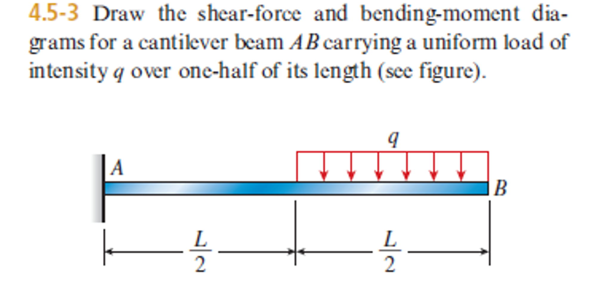
Solved: Draw The Shear-force And Bending-moment Diagrams F… | Chegg.com

Photo Credit by: bing.com / shear moment bending force diagrams draw solved beam cantilever load uniform length problem chegg carrying ab figure transcribed text been
Learn How To Draw Shear Force And Bending Moment Diagrams - Engineering

Photo Credit by: bing.com / shear bending diagram learn exercise structural discoveries erd penjelasannya choice ocw masonry


